Technical data
| Current density: | Up to ± 10 A/cm2 |
|---|---|
| Number of segments | customized |
| Temperature | Up to 200 °C |
| Communication: | CAN |
| Sensorlayer: | Adaptable to your specifications |


| Current density: | Up to ± 10 A/cm2 |
|---|---|
| Number of segments | customized |
| Temperature | Up to 200 °C |
| Communication: | CAN |
| Sensorlayer: | Adaptable to your specifications |
Measure current density and temperature distribution within the cell over the active cell area.
Datasheet download Measurement results download Send request
Delivery time: After consultation
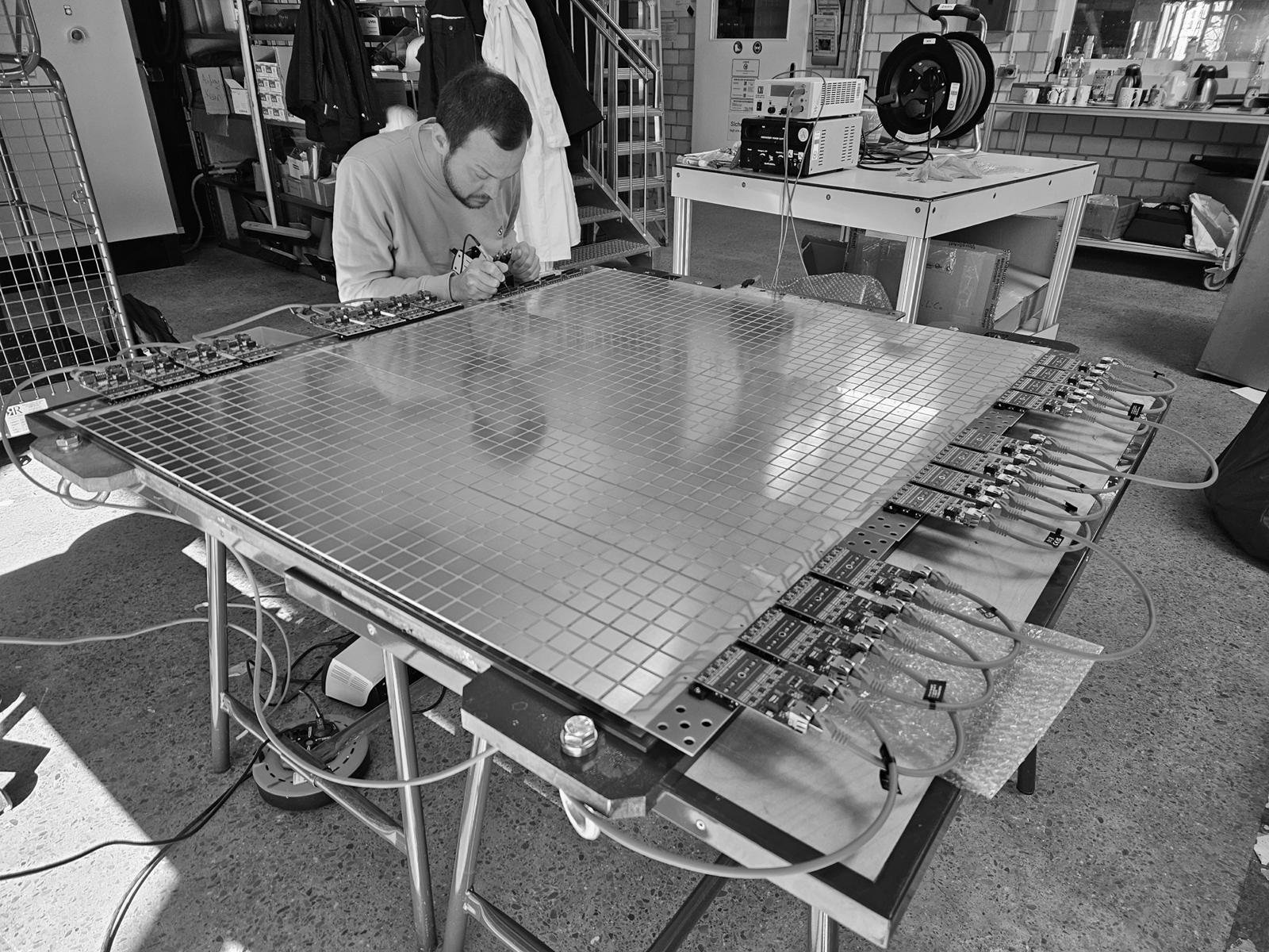
DILICO CURR TEMP consists of a segmented sensor layer featuring current and temperature sensors, electronics for evaluating and transmitting the measured data to the customer's computer, and optional software for visualization and extensive evaluation of the measured values for current density (current strength related to area) and temperature. The segmented sensor layer is integrated between two cells, without direct contact to the gases and liquids. Each segment measures the current and temperature for a portion of the active area of the membrane electrode assembly. The area of all segments is equal to the area of the active reaction surface of the membrane. As a result, DILICO CURR TEMP reveals a two-dimensional image of the distribution of current density and temperature over the area of the membrane-electrode unit.
The activity of the membrane, the design of bipolar plates, seals and other components can thus be evaluated both in operation but also out of operation. During operation, conditions such as gas undersupply, thermal hot spots, and flooding can be identified, directly measure and visualize the correlations between humidification systems and cell performance, and measure the effects of one-dimensional imprinting of AC components by electrochemical impedance spectroscopy on two-dimensional measurement by DILICO CURR TEMP closer to the active area of the cell.
DILICO CURR TEMP thus provides valuable insight into the inside of fuel cells, redox flow batteries and electrolyzers. Use the information to optimize operation and characterize your system. Depending on the membrane area, sensor layer, number of segments and distribution of segments can be individually adjusted according to your requirements to obtain optimal observation of current density and temperature distribution.
Galvanic cells or electrochemical energy converters, such as batteries and fuel cells, generate charge carriers inside at the electrodes. These charge carriers move and an electric current flows to the conductor (cable), which is used to supply electrical loads.
But as the operating time increases, this current continues to decrease because aging occurs at the electrodes and electrolytes. Instead of providing electrical energy, thermal losses increase and increase the heating of the cell.
The current density is defined as current per area (cross-sectional area for current). The unit is given as amps per square centimeter (A/cm²). The background is the comparability of powerful fuel cells or electrolyzers with several 100 amperes per system and smaller cells with a few amperes.
The current density is a measure of the performance of galvanic cells, especially the electrodes on fuel cells, electrolyzers and redox flow batteries. The higher the value, the more electrical power the cell can provide. For the further development of galvanic cells, the values of current density and cell voltage, the two essential electrical parameters for evaluating the condition of galvanic cells, are important during operation.
In electrical engineering, the two values also form the basis of electrical engineering model descriptions of galvanic cells. For research and development, the spatially resolved current density measurement with its many current sensors distributed over the electrode area provides not only one current density value, but when viewed in the area (x,y orientation), many current density values, so that every area of the cell area can be analyzed.
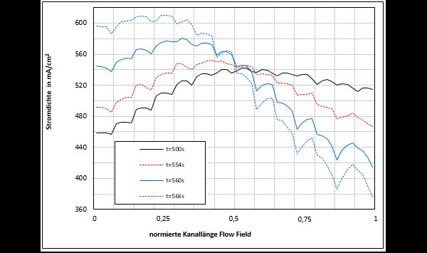
Example: Successive flooding of the fuel cell within 60 seconds at a constant current after reducing the speed of the H2 recirculation pump.
The current density of the membrane areas at the media inlet increase by the value that the current density in the direction of the media outlet drops along the flow channel during the flooding. The membrane in the entrance area now makes up to 600 mA / cm² (previously 470 mA / cm²) compared to about 380 mA / cm² at the output (previously 520 mA / cm²).
A connection between the speed of the recirculation pump and the changed humidity conditions in the output areas of the flow fields could be deduced.
